Construction Details
The basis for the success of prestressed tanks is in two areas. The first is the steel shell diaphragm that is the heart of the wall and which makes the wall impermeable. The second is the bonded prestress wire which is applied under full load giving a uniform, measurable prestress force around the full circumference of the tank. Shotcrete, fully encasing the prestress wire, bonds it to the wall and prevents corrosion.
Sectional informationThe tanks can be divided into the following sections. Click each section for pictures and a description of that part of the tank.
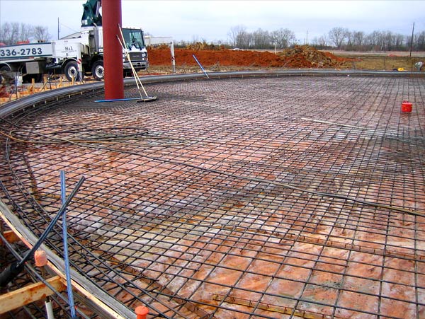
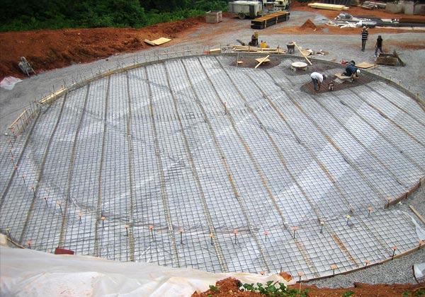
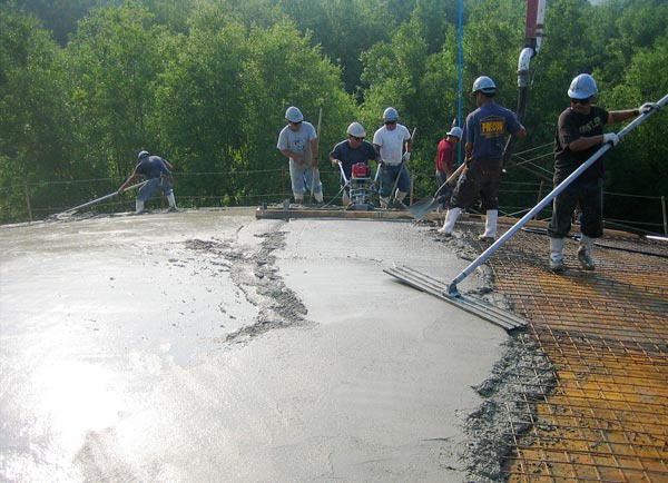
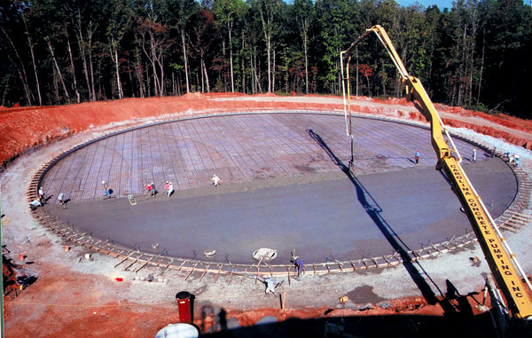
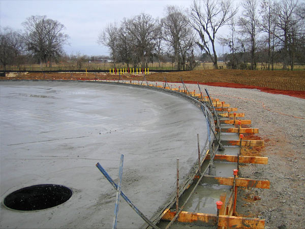
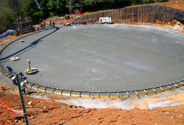
Floor
Our standard floor is a 4" thick reinforced concrete slab designed to act as a flexible membrane slab in accord with AWWA D-110. The floor is vibratory screeded to consolidate concrete and obtain encasement of floor reinforcing steel. After applying a light broom finish the floor is water-cured until tank construction is complete. A highly reinforced 4" membrane slab is able to withstand a maximum differential settlement between the center of the tank and the wall as determined by y= 3 * 10-3 * r2/t (where y = settlement, r= tank radius, and t=floor thickness). Where site conditions generate a differential settlement greater than that allowed by the above equation, a structural floor should be considered. We design and build structural floors for many applications including piles, vibral compaction, rock anchors, tension piles (due to high water table), and ballast slabs (also due to water table).


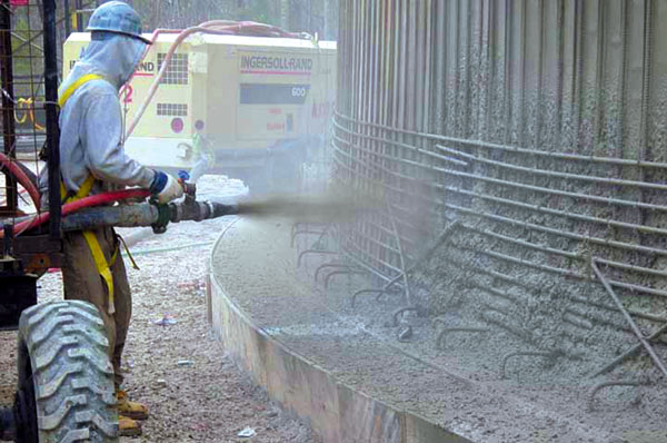
Wall
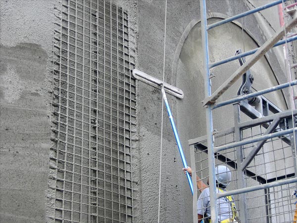
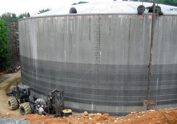
- Core wall The core wall is constructed of shotcrete, encasing a continuous steel shell diaphragm. The thickness of the core wall is designed to accept the initial compressive forces applied by prestressing, backfill, and other applicable loads with a minimum thickness of 3 1/2 inches. The wall typically tapers uniformly on the outside face from top to bottom as required by design computations. The steel diaphragm shall have a minimum of 1 inch shotcrete cover. Interior and exterior surfaces of the core wall shall be water cured.
- Diaphragm A 26 gauge steel diaphragm is embedded in the prestressed wall and epoxy bonded to a PVC waterstop embedded in the floor to form a water-tight wall extending the full height and circumference of the tank wall. The diaphragm is composed of vertical panels fabricated with re-entrant ribs that form a mechanical interlock between the inside and outside layers of concrete. All vertical laps and joints between the diaphragm sheets are sealed with an epoxy sealant.
- Covercoat The final layer of prestressing wires is encased and protected by the covercoat, a minimum of 1 inch of shotcrete applied in a uniform manner and finished to provide a smooth, beautiful, and long lasting light broom finish.


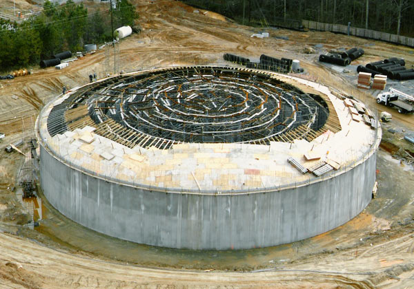
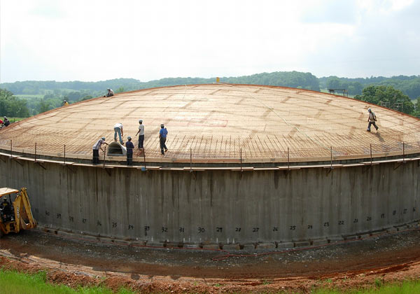
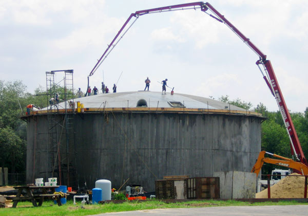
Dome
After shooting the wall we construct a false work of shoring, ribs and plywood decking and pour a reinforced concrete roof in a thin shell spherical shape with a rise of one tenth of the tank diameter. The dome will be a free span, self supporting system with no interior columns of supports after the prestressing process is complete.


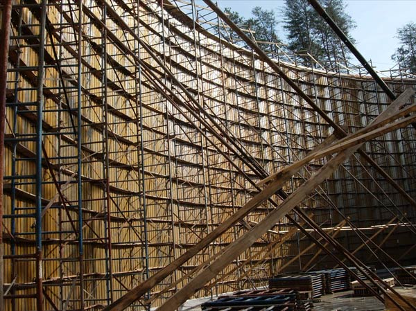
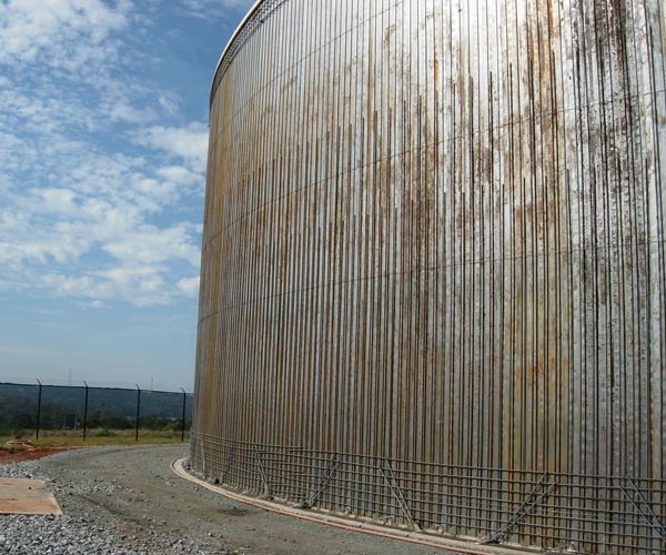
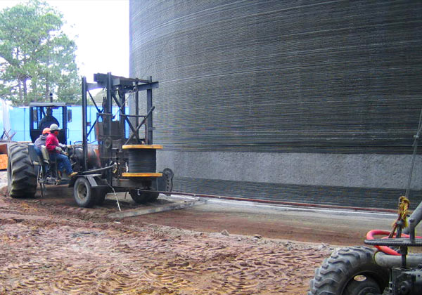
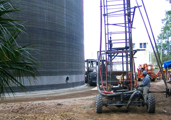
Prestressing
Prestressing is the process of wrapping the tank wall with a continuous steel strand under high tension to keep the tank walls in constant compression even when the tank is filled with water. The placement of the prestressing wire forms a continuous uniform helix of such pitch as to achieve the unit compressive stress required to maintain residual compression of the core wall when the tank is full of water. Extra prestressing in the dome band serves to counteract the radial thrust of the dome weight pushing the top of the wall outward, thus the dome is free standing with no interior supports.


Accessories
The following tank accessories provide accessibility, safety and overall functionality for our tanks.- Fiberglass Inside Ladder (with a S.S. T-S Rail safety device)
- Aluminum Exterior Ladder (with a cage, T-S Rails, security gate, or some combination)
- Fiberglass access hatch cover
- Aluminum handrail around the hatch (or the whole dome)
- Stainless steel wall manhole
- Precast concrete dome overflows
- Fiberglass center vent
- Fiberglass liquid level indicator
- Dome penetrations for instrumentation
- Elevated concrete walkways
- Aluminum stairs, platforms, and catwalks
- Vortex Breakers (over outlet pipe)
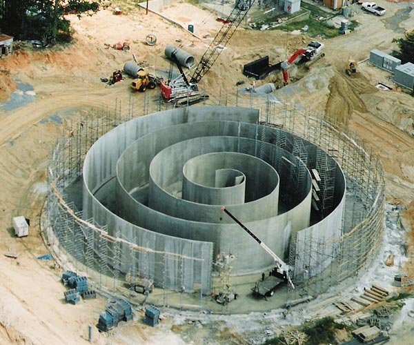
- Tank Baffling, either polypropylene curtain or CMU wall
- Any other specialty item the design engineer may wish to include


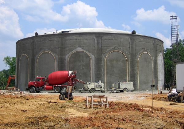
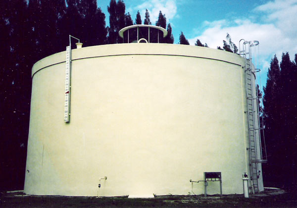
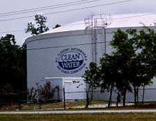
Exterior Finishes
Special exterior finishes may include architectural finishes, special painting formats or unpainted tanks.